
Make Power Pack at a Low Price
Since the commercial power pack was expensive, I made the power pack myself. Although I made the train type transistor controller about ten years ago, it was for long-distance operations. What has me new to exchange and test operation became wanting.
About electricity, since I was an amateur, I worried about what a circuit is carried out. A friend of mine taught that there was a cheap thing. I decided to adopt it instantly.
LM338T, output current is a maximum of 5A. Since the over-current and the protection circuit of heating are built in IC, a circuit breaker is unnecessary and overheat is also the OK outstanding thing.
The parts of a control part are assembled and, therefore, 650 yen is surprise. Although there is also an object (LM350T) for 3A, mere 5A which is generous since it is only somewhat cheap is used. Incidentally it is the same, and although what is using the power transistor is marketed, about 3000 yen and a price are a little high here.
Since what was manufactured this time is planning maximum output 3A, a transformer uses 3A. Otherwise, a chassis (case), a diode, variable resistance, a power cord, etc. are purchased newly. Parts, such as a voltmeter, an ammeter, and a pilot lamp, used the old thing which it already had. It could do for about 10,000 yen, even if it purchases all parts. (A price is the example of purchase in August, 2002 and Akihabara)
|
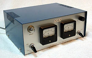
upper left : Pilotlamp lower left : main switch middle left : V meter(DC.20V) middle right : A meter(DC.5A) upper right : controle dial lower right : direction switch There are DC12V out put(for driveing) and AC16V out put(for acceseries). The turminals are on the back side. |
The main point to built
transformer
Although a power supply transformer should just choose a description as reference. It is easy to use what has the tap of 2V unit in a secondary side. It had the tap of 0-16V in the secondary side, and the output used the transformer of 3A this time. The output was set to about a maximum of 12v as a result of using the tap of 16V of that.
change of circuit
kit takes out the fixed voltage, it is changed to fixed resistance (RV of a kit appending circuit diagram), and puts in variable resistance (2k ohm, 1/4W type). Voltage is changed now and speed is controlled. Half-fixed resistance is not used or is made into zero.
By not being completely set to 0V, since the minimum voltage is about 1.5V, two diodes are put into an output in series, and this circuit is carrying out about 1.5v voltage descent.
An alone mass diode is not marketed, but since there was a bridge of cheap 4A, the half is used. Although not still strictly set to 0V, it is satisfactory at all practically. It will OK, if the thing of neutral OFF is used for a polar reversal switch.
Exothermic measure
Since LM338T generate heat considerably so that they stop touching with a finger, a heat dissipation board is required for them. If generation of heat becomes more than fixed, the protection circuit of IC will be worked and downed. It is comparatively expensive although a commercial heat sink and a commercial fan may be attached.
I turn off 1t aluminum board in a suitable size, bend and use it for a box form, and attach it in IC directly with a screw. A case uses entering a slit in order to cope with heat dissipation.
Moreover, it is since the diode extended to the output side also generates heat. The heat dissipation board is attached also in this. It is the optimal method which arrangement is devised and is originally attached in a chassis.
Test run
It tested by connecting two motors (DV18 of KATSUMI and L5 of Kawai) of the old model in parallel. When it operated about 1 hour of continuation with the maximum output (about 0.5 A consumes by 12V since it is no-load), although generation of heat was carried out, it was not downed considerably. It is the effect which made the heat dissipation board more greatly.